
Plastic injection molding is the backbone of mass production for countless industries—automotive, medical, packaging, and electronics, to name a few. But how do injection molding machines actually work?
Introduction
Imagine you drop tiny plastic pellets into a machine, press a button, and out comes a fully formed gear, cap, or housing — precise, consistent, ready for assembly. That’s the magic of injection molding.
From compact 30-ton units crafting delicate parts to mighty 4000-ton giants molding massive structural components, injection molding machines power many of the everyday plastic items around us. Whether you’re a product designer, engineer, or buyer weighing machine options, understanding how these machines operate is essential for making informed decisions.
In this blog, you’ll go behind the scenes—learning exactly how injection molding machines convert raw plastic into finished parts, what sets different machine sizes apart, and what to look for when choosing your next machine.

What Is an Injection Molding Machine?
An injection molding machine (sometimes called an “injection press” or “injection molding press”) is a specialized device designed to turn plastic pellets into finished products through a controlled, repeatable process.
At its core, it does three main things:
- Melt plastic pellets into a viscous fluid
- Inject that molten plastic into a mold cavity
- Cool & eject the solidified part
Because it integrates multiple operations—feeding, melting, injecting, cooling, and ejection—the machine enables mass production with tight tolerances, speed, and consistency.
Manufacturers classify machines by their clamping capacity (tonnage)—which ranges from modest 30-ton machines up to massive 4000-ton (and beyond) units. This tonnage rating reflects how much force the machine can apply to keep the mold tightly closed during injection.
Injection molding machines come in horizontal and vertical configurations, though horizontal is more common in general-purpose manufacturing.
Key Components of Injection Molding Machines
To appreciate how the machine works, let’s meet its main parts—each playing a critical role in turning pellets into parts.
Injection Unit (Plasticizing & Injection System)
- Hopper & Feed Zone: The top “mouth” where raw plastic pellets are loaded (often pre-dried depending on plastic sensitivity).
- Barrel & Heaters: A cylindrical chamber with external heater bands and internal sensors. As pellets travel forward, the barrel temperature is controlled to gradually melt them.
- Reciprocating Screw (or Plunger in older designs): The workhorse. It rotates to push pellets forward, compressing, melting, mixing them. It also acts as a ram to drive molten plastic forward during injection. A check valve or non-return mechanism prevents melt from flowing backward along the screw.
- Nozzle: Connects barrel exit to mold gate. It may be heated or even needle-valve type to control flow.
Inside the screw there are stages: feed → compression → metering. The pellet is gradually compressed, melted, homogenized, and finally held ready in a “shot” volume before injection.
Clamping & Mold Unit
- Fixed Platen & Moving Platen: These two huge plates hold the mold halves. The moving platen opens and closes; the fixed one remains stationary.
- Tie Bars / Tie Rods: Strong steel bars that guide and support the platens, resisting clamping force.
- Clamping Mechanism: There are several types—toggle, hydraulic direct, or hybrid. Its job: force the mold closed and keep it closed during injection.
- Mold (Mold Cavity & Core): The pair of surfaces shaped to form your part. Molds include runners, gates, cooling channels, vents, slides, inserts.
- Ejection System: After cooling, ejector rods, pins, sleeves, or stripper plates push the part out.
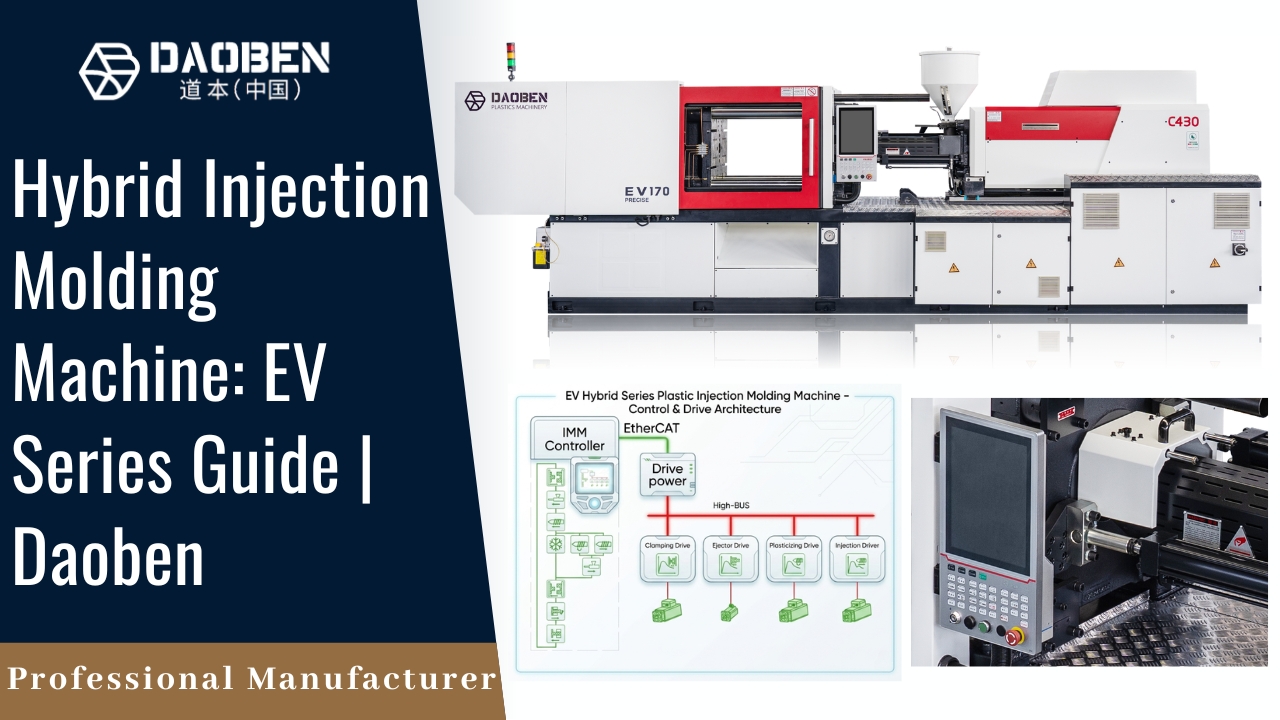
Drive & Control Systems
- Hydraulic System: Uses pumps, valves, cylinders; traditional solution for high force operations.
- Electric / Servo Drives: Increasingly common for energy efficiency, precision, and responsiveness.
- Hybrid Systems: Combine hydraulic force with electric control or servo pumps for optimal efficiency.
- Control / PLC / HMI: Digital brain of the machine—sets temperature zones, injection profiles, clamping timing, diagnostics, feedback, safety interlocks.

How Injection Molding Machines Work — Step by Step
Let’s walk through the full cycle as if you’re standing beside the machine.
- Mold Closing / Clamping
The mold halves are brought together. The clamping unit applies force (the rated tonnage or more) to keep them tightly closed, resisting the internal pressure during the upcoming injection. The machine ensures no leakage (flash) between mold halves. - Plasticization & Shot Preparation
While the mold is closed, the screw rotates inside the barrel. Pellets feed in, melt gradually, mix, and accumulate in front of the screw (metering zone). Back pressure is applied to promote uniform melting and eliminate voids or unmelted particles. - Injection / Fill Phase
Once the screw has accumulated the correct shot volume, it transitions to forward motion (driven by hydraulic or servo) and pushes the molten plastic through the nozzle, gating system, and into the mold cavity under high speed and pressure. This fills the mold. In modern machines, injection is often decoupled: first fill (velocity control), then switch to packing (pressure control). - Pack / Hold (Dwelling)
After the cavity is filled, additional pressure is applied (packing) to compensate for shrinkage as the plastic cools, and to push more molten material into the mold until gate freeze (the point where the gate solidifies). This ensures the part fills properly and has good mechanical properties. - Cooling / Solidification
The molten plastic cools and solidifies inside the mold. Cooling channels inside the mold circulate water or coolant to accelerate this process. Proper cooling is critical: too slow = long cycle, too uneven = warpage or internal stresses. - Mold Opening & Part Ejection
Once the part is solid enough (based on temperature or time), the mold opens. The ejector mechanism pushes the finished part out of the mold. The mold closes for the next cycle. - Next Cycle Begins
While one shot is being cooled and ejected, the screw may already begin rotating and preparing for the next shot—maximizing throughput.
A typical cycle includes clamping → injection → dwelling (pack) → cooling → ejection.
The total cycle time can range from a few seconds for small parts to tens of seconds (or more) for larger or thicker parts—depending on cooling time, plastic type, wall thickness, and mold complexity.
Tonnage Explained — From 30 Ton to 4000 Ton
“Tonnage” in injection molding refers to the clamping force the machine can exert to keep the mold closed during injection. If injection pressure times the projected area of the cavity exceeds the clamping force, the mold will open slightly, causing flash.
How Much Tonnage Do You Need?
A rule of thumb: required clamping force = projected area × factor (e.g. 2–5 tons per square cm, depending on plastic type).
Use Cases Across Tonnage Ranges
- 30–200 Ton Machines
- Ideal for small, intricate parts: electronics housings, medical device components, lenses, toys.
- Low shot sizes, quick cycles.
- Smaller footprint, lower power needs.
- 200–1000 Ton Machines
- Common in consumer goods, automotive interior parts, larger enclosures.
- Can accommodate medium-sized molds, moderately complex parts.
- 1000–4000 Ton Machines
- For large structural parts: outer housings, appliance shells, large automotive bumpers, pallets, industrial bins.
- Requires robust infrastructure (foundation, floor strength, power supply, cooling).
- Slower cooling and heavier molds increase cycle times and complexity.
When choosing tonnage, it’s crucial to match it to your part’s projected area, wall thickness, plastic type, and injection pressure. Oversizing can waste energy; undersizing can cause defects.
Differences Between Small and Large Injection Molding Machines
While the basic working principle is the same, there are practical and operational differences between small (e.g., 30–200 Ton) and large (e.g., 1000–4000 Ton) machines.
1. Mechanical Strength & Rigidity
Large machines must resist enormous internal pressures. Their frames, tie bars, and platens are massive and built for minimal deflection under load.
2. Mold Complexity & Scale
Bigger molds often include multiple cavities, inserts, slides, heating/cooling zones, and may require more advanced mold cooling and venting strategies.
3. Cycle Time & Heat Removal
Because of thicker walls and larger volumes, cooling is often the slowest part of the cycle on big parts. Efficient cooling channel design and uniform flow matter more.
4. Power Consumption & Infrastructure
Large machines draw high current and need strong power supply lines. They also generate more heat, needing robust HVAC or coolant systems.
5. Maintenance, Cost & Footprint
Spare parts cost more, alignment tolerances can be stricter, and the footprint (floor space, crane access) is significantly larger.
6. Automation & Control Needs
At high tonnages, process control, sensors, closed-loop feedback, and safety systems become even more critical to avoid waste or mold damage.
Despite the differences, both small and large machines share the same cycle stages—just scaled differently.
Modern Innovations in Injection Molding Machines
The injection molding industry is evolving fast. Here are some current trends and technologies:
- Servo Motor & Electric Drives
These drives consume much less energy (sometimes up to 80% savings) and offer high precision in speed and position. - Smart Monitoring & IoT Integration
Machines now have sensors monitoring pressures, temperatures, vibration, alarms. Real-time data lets you predict maintenance or catch defects early. - Closed‑Loop Control & Adaptive Algorithms
The machine dynamically adjusts injection speed, pressure, or pack time based on sensor feedback for consistent quality. Some research is pushing into AI / deep reinforcement learning for self‑optimizing control. - Rapid Heat Cycle Molding / Steam Assist
This technique rapidly heats mold surfaces before injection, then cools after filling to improve surface finish, reduce weld lines, and shorten cycle time in some cases. Wikipedia - Gas-Assisted Injection Molding
A small amount of inert gas (often nitrogen) is injected into the melt to push it into mold extremities and help form hollow or semi-hollow sections—useful for thick parts or weight reduction. - Multi‑Shot / Overmolding / Insert Molding
Machines with multiple injection units allow combining different materials/colors or embedding metal parts during molding (e.g., overmolding a soft grip on a rigid core). - Simulation & Digital Twins
Advanced mold-flow simulation and digital twins help optimize gate location, cooling channels, and cycle times before physical tooling begins.
These innovations help manufacturers reduce energy, scrap, cycle times, and improve part quality.
Applications Across Industries — Real World Examples
Here’s how different industries leverage injection molding machines across various tonnages:
- Automotive
Bumper skins, instrument panels, interior trim pieces, engine covers. Many large automotive parts require machines over 1000 ton. - Consumer Electronics
Smartphone bodies, remote control housings, connectors. These often use compact, high-precision machines in the 30–200 ton range. - Medical Devices
Syringes, diagnostic housings, surgical instrument handles—small, highly regulated parts requiring tight control, often in smaller machines. - Packaging & Containers
Caps, closures, bottles, food containers—these use fast cycles on mid‑sized machines. - Appliances & Industrial Goods
Household appliances housings, electrical outlet boxes, structural parts—these may need mid-to-high ton machines.
Every industry has its sweet spot in the tonnage range, guided by part size, complexity, throughput goals, and material.
Tips for Choosing the Right Machine for Your Business
To get the best ROI and production efficiency, consider:
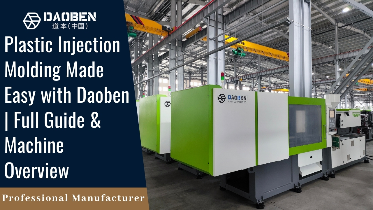
Daoben Machinery is a professional plastic injection molding machine manufacturer and supplier. Producing injection molding machines of 30 Ton to 4000 Ton
- Projected Area & Injection Pressure Requirements
Always calculate required clamping force based on your part’s projected area and plastic’s fill pressure. - Shot Size & Utilization Rate
Choose a machine whose shot capacity aligns closely (not excessively higher) to your required shot to maximize efficiency. - Mold Size & Complexity
Your molds may need slides, lifters, inserts, cooling circuits—ensure the machine can support those. - Energy Efficiency & Drive Type
Servo-electric or hybrid machines reduce energy and improve control—especially valuable in high-volume production. - Support, Spare Parts & Service
Working with a reliable manufacturer means you get quicker replacement parts, better training, and long-term machine health. - Factory Infrastructure
Consider floor strength, power supply, cooling water capacity, crane or hoist access, safety layout. - Scalability & Flexibility
If your product line may grow, choose a machine that gives you headroom without overspending.
Summary
The journey from raw pellets to finished plastic parts is a carefully orchestrated dance of heat, pressure, timing, and mechanical precision. From 30-ton machines handling delicate precision parts to 4000-ton presses forging massive structural components, the underlying principles remain the same—just scaled differently.
Understanding all the elements—from the screw and barrel to mold design, clamping force, cooling, and control systems—gives you the insight to choose, operate, or optimize injection molding machines for your products confidently.
Frequently Asked Questions (FAQs)
Key components include the injection unit, clamping unit, mold system, and drive system (hydraulic, electric, or hybrid).
It depends on the surface area of your part and the material used. Higher surface area or stiffer plastics require higher clamping force.
Common types include ABS, PP, HDPE, Nylon, and PC.
It ranges from 10 to 60 seconds, depending on part complexity, material, and machine size.